Step by step illustrations are easy to follow. A special section on winding the spring will also be found here.
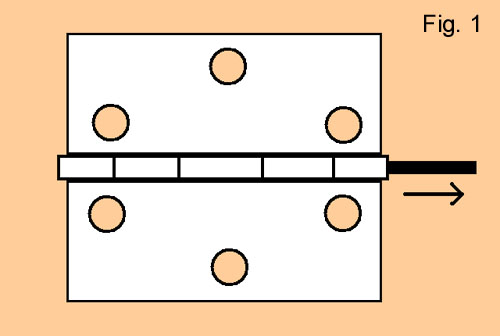
Fig. 1 below shows a typical tight pin hinge. You must first knock out the pin. Clamp one wing of the hinge in a vice, with the pin barrel verticle. Use a nail or another similar object to knock the pin out. Tap the nail with a hammer, driving the pin out the opposite end of the pin barrel. Retain the pin for later use.
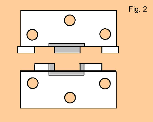
Cut away all areas shaded gray (Fig. 2). The extra space is needed to accommodate the spring.
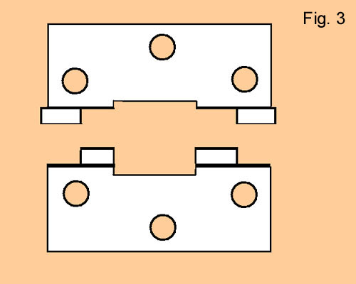
This shows the two sides of the hinge after the areas have been cut away (Fig.3).
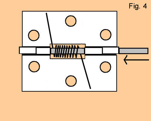
This shows the finished hinge with the spring already in position. The pin is being driven back in (Fig. 4).
Not shown in the drawing is the fact that I slightly bend the end of the pin before it goes in. The bent area is always last to enter the pin barrel. This will serve to lock the pin in place.
The spring winding process is as follows: (Apologies for some of the photos being out of focus.)
You will be winding the wire around a post. The best thing to use is the pin from the hinge, but a similar diameter rod or nail of any kind will do. Clamp it firmly in a vise toward the right side and positioned vertically One end of the wire must be secured before winding. I clamp it firmly to the vise as shown, using a Vise Grips. Be sure to leave a long enough "leg" before the wire reaches the winding post. You will trim the excess later. Fig. 5 shows how everything is clamped. Fig. 6 is a close-up of the wire for clarity.
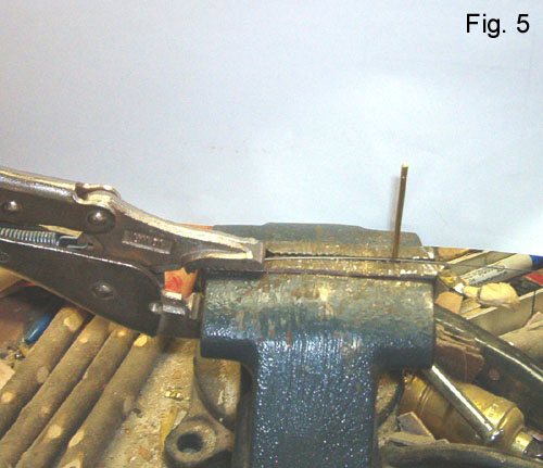
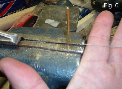
Fig. 7 shows the winding process under way. The wire is wound tightly (emphasize, tightly) around the post counterclockwise. It could be done either way, but this has proven easiest for me.
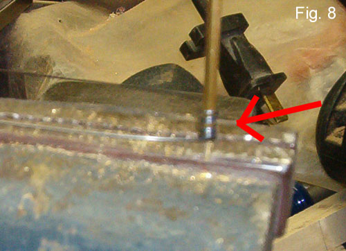
The arrow points to the coil, and note that the coils are spaced apart. I did this intentionally incorrectly for this illustration. The spring's coils should not be spaced apart, but as close together as possible. It makes the spring easier to control later, and you can fit more coils into the allotted space. More coils will produce a better spring, as the tension is distributed over a larger area. This reduces the possibility that using the spring will undesirably alter the tension.
Should the coils be spaced too far apart, push them tightly downward, using your thumbnails, or a tool with an edge.
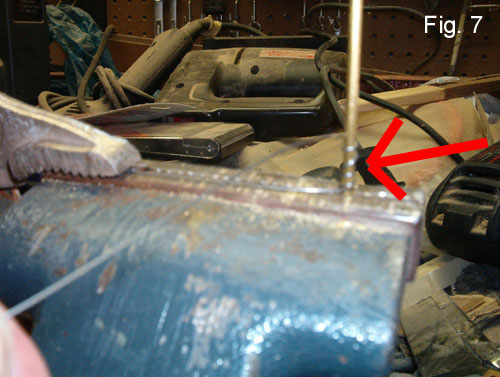
Fig.8 shows the coils pushed more closely together.
VERY IMPORTANT!!!: Do not let go of the end of the wire during the winding process!!!
It may unwind with force and possibly injure you. At the very least, the coils will loose their tension, and render the spring very difficult to finish, if not useless.
After you have wound the desired number of coils, and this will depend upon the spring you are making and its intended use, you will finish the winding so that when you release the tension, the legs form an angle of less than 180 degrees. You will find it easier to set the spring into the hinge later, if that angle is obtuse, rather than acute. This will still create enough tension for the hinge to work correctly. If the spring must be tightened a lot when setting it in, it will make your job very difficult and frustrating.
Because the spring will naturally want to unwind a bit when relaxing it after winding, this must be taken into account when deciding how the legs should be positioned when you stop winding. In other words, after the legs relax and unwind a bit, you want them positioned so that the spring would have to be wound tighter, not unwound to make them point in opposite directions. What this will do is make a spring that, when fitted into the hinge will cause the hinge to already have some tension on it if the wings of the hinge are open and spread opposite each other. Closing the hinge would tighten the spring even more. Do not try to straighten, or unwind any coils that you have already made. If you have gone too far, first try to go one more coil, stopping in a different position. If this would make the spring too long to fit the space cut from the pin barrel, it will take less time and produce better results to just start over.
You may have to experiment to understand exactly how far to wind the wire before stopping so that when it is allowed to relax, the legs will be positioned correctly.
When you are ready to relax the coils, do so slowly enough that you'll get a good sense on how much it will unwind. If you have pulled the coils tightly during the winding process, this will be minimized. This is partially for safety, and partially to see if you have stopped at the correct position. Relax the wire completely, and remove everything from the jigs.
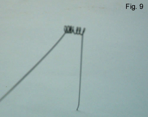
Fig. 9 shows the finished spring.
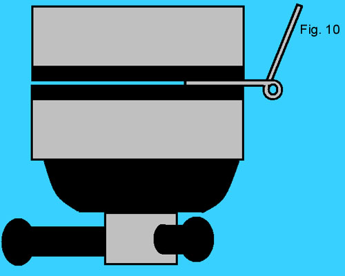
To insert the spring into the hinge, you must clamp one of the hinge wings in the vice. I do this on the right side of the vise, with the pin barrel to the right and vertical. Fig. 10 is a top view.
Note the orientation of the barrel in relationship to the wing. The drawing also shows how the other, non-clamped wing should be positioned. If the pin were in place, the unclamped wing would turn clockwise to close the hinge. Turning it counterclockwise, the hinge would eventually bind.
From the top, set the pin into the barrel to lock the two wings together, but stop just short of the pin coming into the open, cutaway area. Orient the spring into the open area of the hinge, so its legs are relatively parallel with their corresponding hinge wings. Make sure that if the hinge were to close, the spring would tighten.
With the spring pushed into the open area and its open ends lined up with the pin barrel, drive the pin through the spring, and into the rest of the barrel. You will probably have to adjust the alignment as you come to each new section and opening. As was mentioned earlier, if you have put a very tiny crimp in the pin, near the end that goes in last, it will finish with a tight fit that will prevent the pin from accidentally falling out in the future.
Check the hinge to be sure that it operates correctly without binding. When satisfied, trim the legs of the spring, but do not cut them too short. Fig. 4 shows a reasonably good length.
The process and illustrations show this spring hinge being built from a hinge with a five-part pin barrel (three sections on one wing, and two on the other). This allows for the center section of the three section wing to be cut completely away without compromising the stability of the hinge. This also affords the maximun space being created to house the spring. It should be possible to construct a spring hinge with a four part pin barrel, but care must be taken that sufficient amounts of the barrel remain that will allow the hinge to function normally and securely.
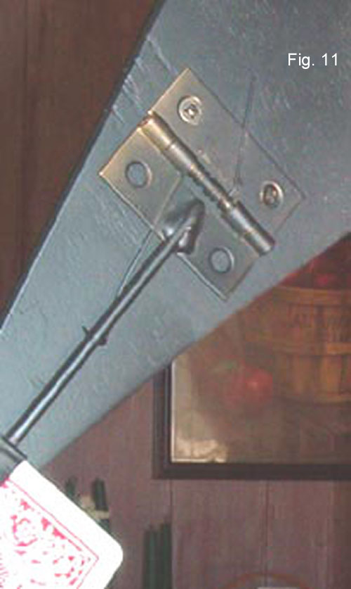
Fig. 11 shows a completed spring hinge in place on the back of a card star. Notice that the leg on the arm side has been extended, and actually wraps around the arm for greater leverage.